In this project, we obtain Level 3 SPICE simulation parameters from measured data of our device, and apply them to the following basic circuit. Level 3 variations are given extensive considerations.
DCsweep, Transfer Characteristics, and Output Characteristics measurements are made on our project circuit, which follows. Rb is made a smaller value for Xfer and Output characteristics, for example about 1k.

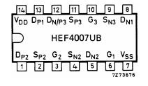
NMOS is from this chip, pins 6, 7, and 8.
Measured data are stored as Global Variables.

Parameters – Extraction always uses the Level 3 Version as to be applied. The ![]() selection applies to the simulation step shown just below. It selects by way of the Global Variable
selection applies to the simulation step shown just below. It selects by way of the Global Variable ![]() (binary) K= 1 or K=KAPPA, for AIM spice or LTspice, respectively, for the Ep form. (PSpice uses KAPPA.) The button
(binary) K= 1 or K=KAPPA, for AIM spice or LTspice, respectively, for the Ep form. (PSpice uses KAPPA.) The button ![]() when selected to binary 1 sends a parameter file for the simulators. Upper UCRIT vales are for K = KAPPA, lower values are selected for K = 1.
when selected to binary 1 sends a parameter file for the simulators. Upper UCRIT vales are for K = KAPPA, lower values are selected for K = 1.


Ep is used in the final Level 3 simulator stage. An alternative is to assign Ep according to other uses, including Ep = 0.

Curve fit to xfer characteristic X, for UO, sum. Slope fit finds VTO.

Slope fit to oc, sat region, finds KAPPA.

Sample NMOS Parameters – This runs under N_P_pars.vi above.

Measured amp data, Global Variable, DCSweep, sample.

DCsweep with Level 3 simulation. Note that Data oc is approximately mid range to the application range. Here, the LabVIEW simulator uses Ep = 0 (lc = 0) or Ep = Vdsat/Leff, with similar results. This is equivalent to basic Level 3 (VMAX = 0) for the output (channel-length modulation) but here, the effect of velocity-saturation effect is still present.
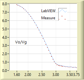

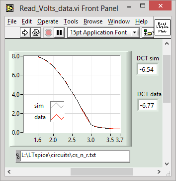
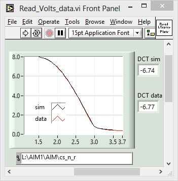
Following are Simulations comparing LabVIEW with AIM spice and LTspice, based on their respective versions of Level 3 SPICE. The simulators are discussed, for example, here. In the above LabVIEW simulation, Ep = Vdsat/Leff.


Compare simulation, LTspice, with data, and AIM spice with data.